The Train Catcher is a simple device which goal it is to receive or ‘catch’ an analog train and to let it depart. A Train Catcher is not an automatic shuttle unit on it’s own, but it can be used to control a manual operated, semi-automated or fully automated layout with or without shuttle services.
What does it do?
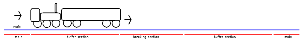
A Train Catcher ‘catches’ inbound trains. To do so it has three track sections. The buffer section, brake section and stop section. The brake section has feedback and once triggered the Train Catcher will start slowing down the train. In the most basic setup, the breaking section is the only section needed.
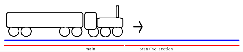
With a potentiometer the breaking distance can be fine tuned for every Train Catcher.
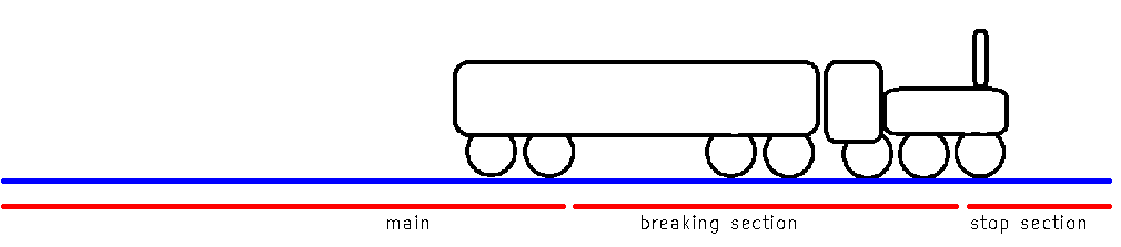
The stop section also has feedback and when triggered the brake process is accelerated by a factor. This has the purpose to better align trains with different driving properties along side the platform. It is optional to use. If your trains all have similar driving properties, you could leave the stop section out.
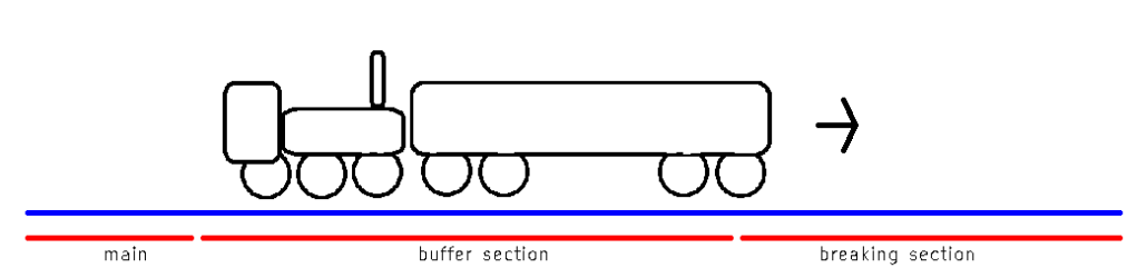
The buffer section is intended for push-pull trains. It allows a pushing locomotive to enter a section of switched tracks before the Train Catcher starts slowing down. This will prevent any speed jumps. Once the first wagon reaches the break section, the pushing locomotive will already be on the buffer section.
Reversing polarity
There are two methods to let a Train Catcher to depart his train. The first method is done by switching the tracks’ polarity. Once a train has stopped, the Train Catcher will allow short pulses on the track. These pulses are too short to let the train move but are long enough for the current sense circuit to detect the train. Because DC type optocouplers are used, the current sensing only works only in one direction.
This means that as soon as the polarity reverses, the Train Catcher will no longer sense the train. At that point the Train Catcher will start to accelerate the train in the direction of which it came from.

With two Train Catchers and a method to reverse track polarity you can let one train shuttle.
Stops along the line
The other method of letting a train depart, is to make use of the hold line. This is an input which is used to hold down a train. By releasing or pulsing this line, a Train Catcher will let his train depart. This is usefull for having several head tracks to operate more than just one train.
But besides using more trains, the hold line can also be used to make stops along the line. Using the hold line is regardless of direction. This means that you can let a train resume it’s route after a pause.
For a pause it may be needed to apply an extra buffer section after the breaking section. This depends if the train has enough time to accelerate on the breaking section. The added buffer section is here ment to let a train reach 100% before reaching the main tracks.
It is also possible to let the Train Catcher work in both directions. This can be achieved by using an AC type optocoupler chip instead of a DC type. Than it can sense current in both directions

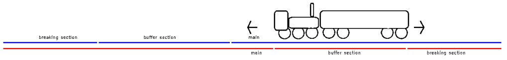
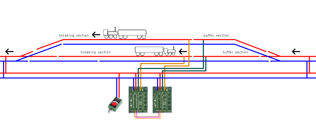
In above image, I use three buffer sections, abreaking section and a stop section. The breaking and stop sections are ambigous. Which sensor is triggered first becomes the actual breaking sensor and the other sensor automatically will be the stop sensor. By adding a buffer section between the breaking and stop section you can align trains along a platform from both directions. This does require six cuts in track which may be undesirable
Automatic operation
After a Train Catcher has ‘caught’ or received a train. It will transmitt a brief pulse. This pulse can be used to do numerous things like toggling a timer relay, setting points or signals or letting other Train Catcher depart their trains. Or it does all these things at once.
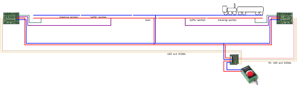
To supplement the Train Catcher, I also made a simple timer relay. This relay is capable of reversing track polarity. So with two Train Catchers and one timer relay, you can already make a fully automatic shuttle service.
To automate a departure after a pause you can connect the hold line to the signal line. If the hold line is tripped when the Train Catchers sends the received signal. The Train Catcher will let his train depart in 30 seconds, discarding track polarity. This is the easiest way to make a pause along the line.
If you want a different time than 30s. You could also use a timer relay to pulse the hold line as the timer relay is adjustable with a potentiometer. But I also made a cheaper module for this using a 555 timer. This module can be triggered with the signal line and will hold down the hold line for an adjustable amount of time (depending on a potentiometer). After the time expires, the 555 module will release the hold line. This will let a train depart. The module can be directly stacked on the 4-pole header
You could also simply use a push button to let the train depart manually.
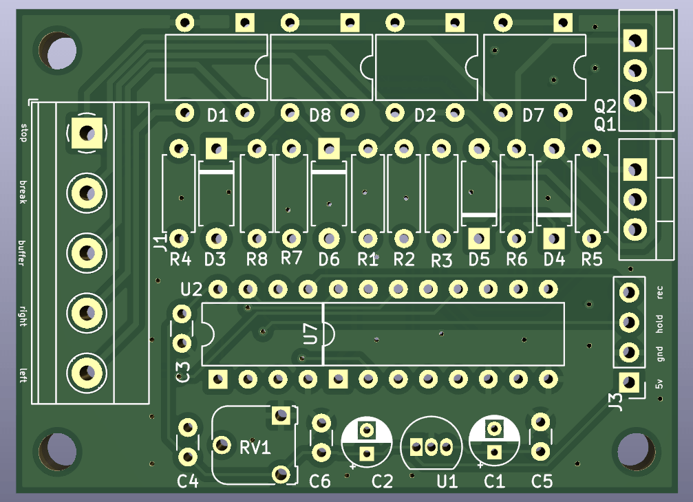
Connecting a Train Catcher
A Train Catcher has two rows of connectors. You have the blue screw terminals on one side and one row of headers on the other side. The screw terminals have connections for all the track sections and the mains. The right rail, left rail, buffer section, breaking section and stop section are all present.
The pin header has four connections for ground, 5V output, signal line and hold line. The signal line is the line which transmitts a signal. You can use this signal line to trigger a timer relay. The hold line can be used to hold down a train. As long as this line is tied to ground, no train will depart. Only when this line is released, a train will depart.
One of the greatest features of a Train Catcher is the ability to work with manual switches as well as with timer relays. Reversing the track polarity can be done with a single DPDT switch. But the track polarity can also be reversed automatically with a timer relay. Just what you want to do.
After a Train Catcher ‘caught’ a train, it transmitts a signal. This signal can be used to trigger the timer relay. With this relay you could reverse track polarity but you could also use the relay to signal other Train Catchers. This allows you to make more complex layouts.
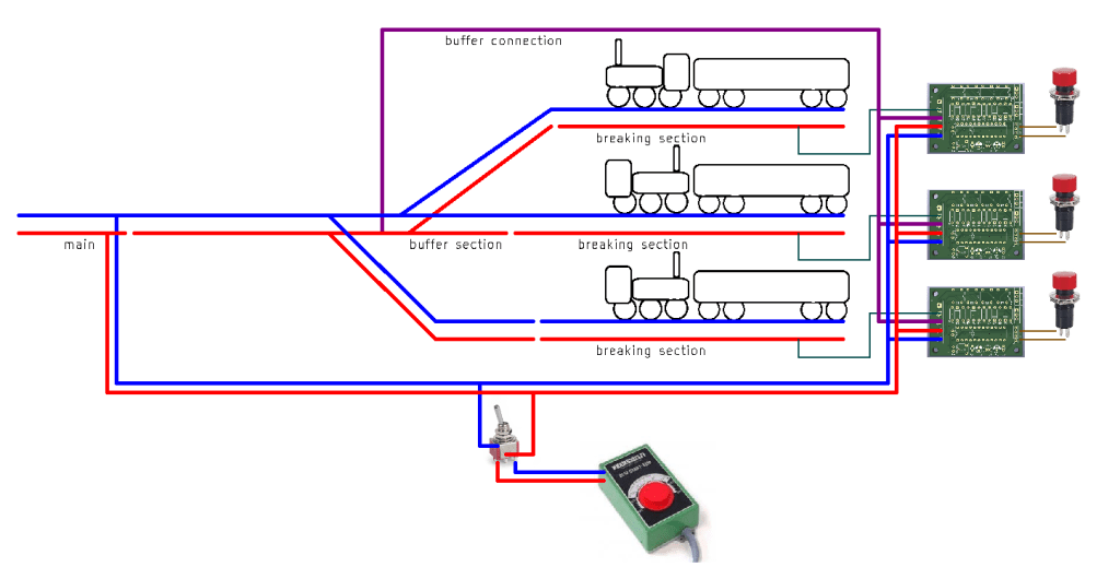
In this example you see three terminal tracks. A switch for track polarity and three pusbuttons. In order to let one train depart you first have to set to polarity to left and than you can use one of the three push buttons (normally closed) to select which train may depart.
Take note that buffer section is now one section which is shared by all three Train Catchers. This is possible to do and saves space and making more cuts in the track. There is only one but. Sharing a buffer section only works if there is only one Train Catcher receiving a train. If two or more Train Catchers are expectiving a train both will keep the buffer section switched on. In this example the stop sections are also not shown.
Connecting a timer relay
The timer relay requires a 5V supply and ground connection to operate. Every Train Catcher outputs 5V and ground and you can use any Train Catcher to power a relay.
The timer relay has two signal inputs, one for setting the relay and one for resetting the relay. You can also tie the set and reset to eachother, this will cause the relay to toggle.
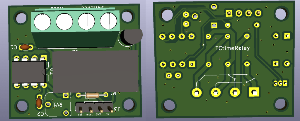
The relay contacts are arranged specifically for reversing track polarity. However you can do with them whatever you want. They can be used to set a signal, a point or a decoupler.
You can connect a timer relay to a Train Catcher as follows:
After a train is ‘caught’ the signal line of one of the Train Catcher will let the timer relay toggle after an adjustable amount of time, causing the train to automatically drive back. Both Train Catchers will let the timer relay reverse the polarity which causes the train to shuttle back and forth periodically.
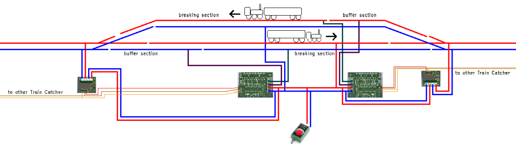
The following example shows how to make a passing section. The polarity on both Train Catchers never changes because the trains always drives in the same direction. Each Train Catcher triggers their internal pause time of 30 seconds and they will toggle the main track polarity of the section ahead.
Note that this solution has two minor flaws. Each train much reach his pausing locations within 30 seconds of the other train. There is no interlocking between the Train Catchers. The other flaw or ‘difficulty’ is that each relay needs to be fine tuned to work with the 30s delay. There is some marge of error, but the relays must be set before departing trains reach the main tracks. And the relays must not be set before the other train has arrived.
If the trains need to rotate in a fiddle yard, you can let Train Catchers depart eachother trains. This example does it with just two trains, but this can be done with infinite tracks. If the bottem train has stopped, the signal of the bottem track’s Train Catcher will signal the other Train Catcher to depart.
The pause module (work in progress)
The pause module is a simple extension which you can directly plug on the four-pole terminal of a Train Catcher. With this module you can configure a pause time for a train. The circuit uses a 555 timer in ‘one-shot’ configuration. After it receives the signal of the Train Catcher it will start holding down the hold line until the time expires. Than the train will accelerate again.
Setting points
The signals emitted by the Train Catchers can also let Servo Drivers move points or semaphore signals. You could also use a timer relay to control magnetic point motors (provided that these shut off mechanically)
In order to more points at once you can make use of a diode matrix.
