DISCLAIMER. This webpage is solely ment for when you ordered my designs directly at the PCB manufactorer. Decoders sold by myself are all ready-to-run products. It is also useful for when you want to update a decoder for a bug-fix or feature update.
Prelude
Programming any Train-Sciece DCC decoder has to be done via a method which is called In Circuit Serial Programming or ICSP for short. The Arduino website has a very elaborate explanation how that works and how you can do this. I have a shorter tutorial however. It does involve using a computer.
One final note. This page was originally written for the first decoder named OSSD, but the process is the same for all Train-Science decoders and every other Open-Source design that require firmware.
Step 1: Download the necessary files.
If you have not yet download the Train-Science DIY repository, it is time to do so now.
In order to download the files you need. You need to download the entire Train-Science-DIY repository. Click on this here link, click on the green code button and click download ZIP.
Once the zip file is downloaded, it should be in your computer’s download folder. You need to extract it first. Right click on the zip-file and click extract or extract all.
Make the connections
A Train-Science decoder cannot be connected to a computer directly. In order to do this we need to use an Arduino board.
The first thing we must do is, is to make the connections between Arduino and decoder. Make sure that the Arduino is not plugged in the computer while you connect the wires.
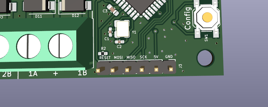
Every decoder has an ICSP connector for programming. In order to connect the wires. You could solder a conventional pin connector on it. The pins are marked so it should be easy to hook it up to an arduino. You can simply use depont wires for this. Alternatively you can purchase a so called pogopin clamp. This allow you to program without the need of a soldering iron.
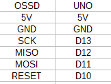
You need to make the following 6 connections between decoder (OSSD in this case) and Arduino board.
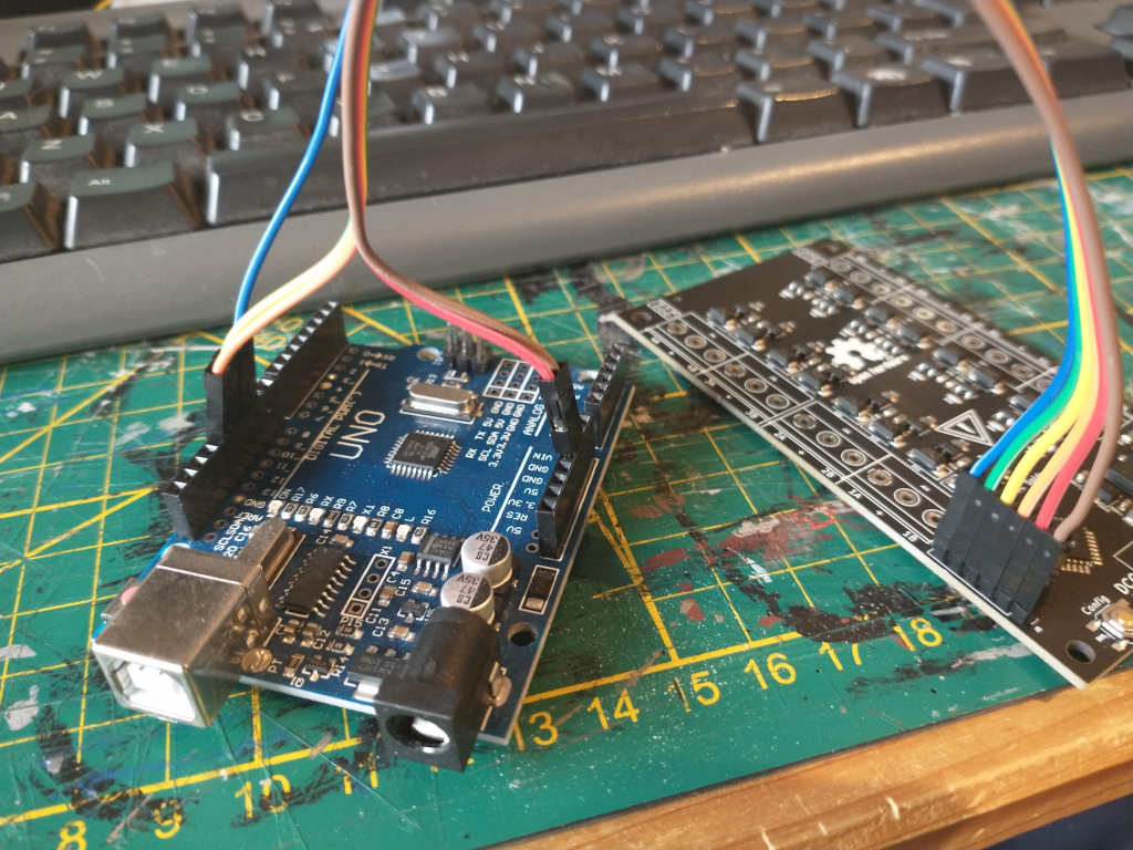
When the Arduino is connected to the decoder you can plug it in the computer via an USB cable.
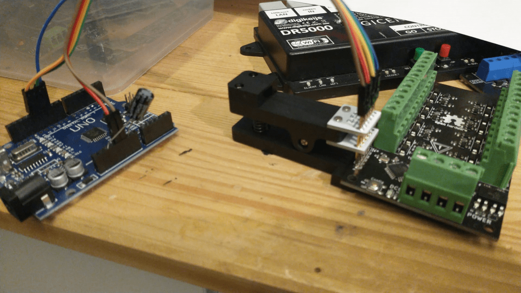
If you intend to do this often you may consider buying a 1×6 pogo pin clamp in 0.1″ or 2.54mm pitch. With it you don’t have to ‘do’ the wires and solder the program connector. This clamp has conical pins which are pressed against the program connector with a spring.
Flash the ArduinoISP program
The second thing we need to do is turn this Arduino board into a programmer by flashing Arduino’s ‘ArduinoISP’ program into the board. When that is done we can use the Arduino board to program the OSSD.
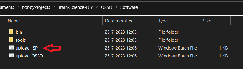
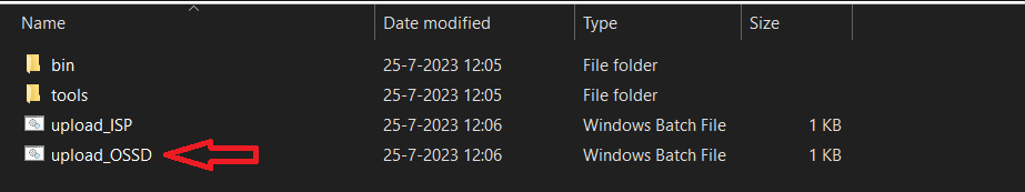
For both programming the Arduino and a decoder there is an easy way and a slightly less easy way. The easy way is as simple as clicking on “upload_ISP.bat” in the software folder.
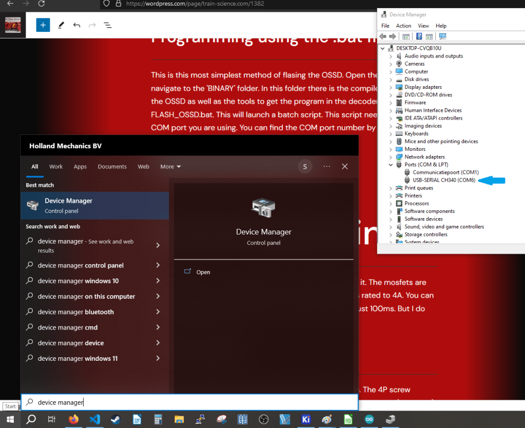
This will open a window which prompts you for a COM port number. You can find all attached COM ports in the windows device manager. Looks for something that says something like CH340 or FTDI.
Enter the COM port number* and hit Enter. If all goes well you should see the following.
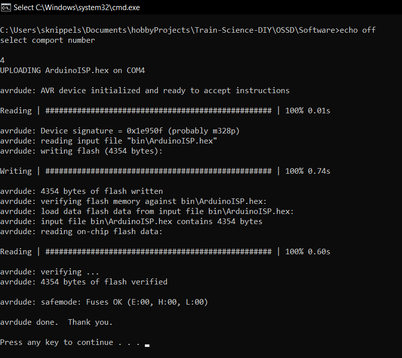
This was the easy way. 2 mouse clicks and 2 button presses.
*Note, the latest script can automatically recognize the comport for us. This brings the intensive labour back to two mouse clicks
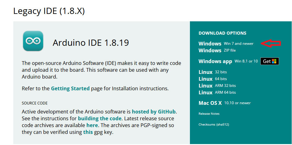
The less easy way involves downloading and installing the Arduino IDE on your computer. It is a fairly simple process you can just surf to arduino.cc, click “software” and navigate down to Arduino IDE 1.8.19
Once installed you need to open the example sketch named ArduinoISP and flash it into the Arduino board.

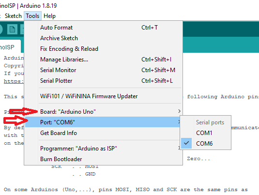
Make sure to set the COM port and board settings right. You can see which COM ports are available in the IDE. It is usually the bottom one. Set board type to UNO (or NANO depending on what you bought)
Finally click on the upload arrow.

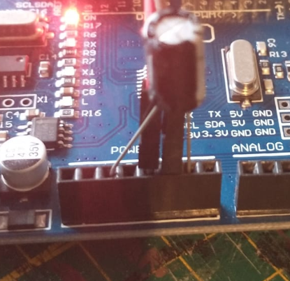
When the Arduino is programmed it is almost ready to be used as programmer. You need to put in a capacitor in the Arduino (10uF or more). The long leg (+) should go in the reset pin and the short pin (-) should go in a GND pin. This capacitor prevents the Arduino from being reset when we try to program the decoder.
Once you have succesfully programmed the Arduino board with the ISP program, made all the proper connections and inserted the capacitor, the programming of the decoder can now commence!
Flash the Decoder
Like before there is the easy way and the slightly less easy way. Again the easy way exists out of double clicking one of “upload_xxx.bat” files in the software folder and entering the COM port number*. If that goes well you should see a similar result as before.

*Note #1 as mentioned earlier, newer scripts come with automatic COM port detection.
Note #2. It can occasionally happen that the upload process sometimes fails. Sometimes it tosses an error sometimes it does not an error and the board won’t work. When it happens, just keep trying it again until it does work/
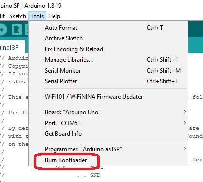
With the Arduino IDE method, you need to do 2 steps. Before you program the board with the a Decoder program, you’ll first need to burn the bootloader. This is also explained on the Arduino website. It is however incredibly simple… You can just click on ‘Tools’ and ‘burn bootloader’. Also make sure that board and COM port settings are correct.
Extra information: The bootloader is usually needed for an arduino to allow programming via USB. However it is also important because it sets the Atmega’s fuse bits to work with the correct clock frequency. If you don’t do this the decoder will operate at 1/16 speed and won’t be able to do decode a single DCC message.
When the bootloader is ‘burned’ you must open a decoder project in the Arduino IDE. You can do this from within the IDE itself via ‘File’ -> ‘Open’. Or you can navigate to the appriopiate decoder source code folder in the explorer and double click on the xxxx.ino file. This should open the IDE for you with the desired program open.
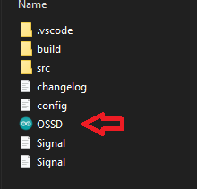
This is what you should see now.
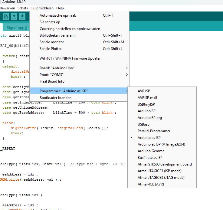
In order to program a Decoder program into the Decoder we won’t be using the conventional upload method with the arrow. You need to tell the IDE that we will be using an Arduino as ISP programmer. You can do so by clicking on ‘Tools’-> ‘Programmer’-> ‘Arduino as ISP’.
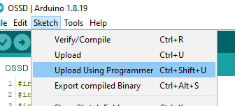
Than you you must click on ‘sketch’ and ‘Upload Using Programmer’. Or simply hit the shortcut Ctrl + Shift + U.
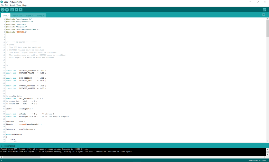
Doing so will let the Arduino IDE first compile the program and flash it into the Decoder. If you see this message in the bottom of the IDE.
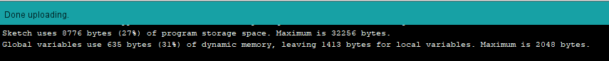
It means that you have a fully operational Train-Science Open-Source DCC decoder in your hands.
